2006/04/01

Pulsed DC脈衝直流電源不同應用的組合

1. 雙極對稱式輸出
這種組合主要用在同靶材的反應式雙磁控濺射靶的鍍膜製程。SiO2, TiO2, Ta2O5, Al2O3, ITO, AZO等。利用改變脈衝作用與非作用的時間來控制濺鍍電漿的密度高低,在特定的電漿阻抗條件下,可優化濺鍍速率與薄膜品質。組合如下:
1.1 脈衝產生控制器 X 1
型號MAGPULS 1000/30/100 bp
• +/- 0-1000V輸出
• 30安培直流輸出(Max.)
• 100安培脈衝電流輸出(Max.)
1.2 直流電源供應器 X 1
型號MAP 1000/20
• 0-1000V輸出
• 0-25安培直流輸出(Max.)
註:在400伏特的濺鍍製程有最大電流輸出25安培。


2. 雙極非對稱式輸出
這種組態大量用在單靶的反應式濺鍍製程以及氮化物硬膜的治具偏壓用途。也有用於雙靶特殊混合的陶瓷合金濺鍍製程。組合如下:
2.1 脈衝產生控制器 X 1
型號MAGPULS 1000/30/100 bp
• +/- 0-1000V輸出
• 30安培直流輸出(Max.)
• 100安培脈衝電流輸出(Max.)
2.2 直流電源供應器 X 1
型號MAP 1000/3 (供應正電壓)
• 0-1000V輸出
• 0-3安培直流輸出(Max.)
2.3 直流電源供應器 X 1
型號MAP 1000/20 (供應負電壓)
• 0-1000V輸出
• 0-25安培直流輸出(Max.)

2006/03/27

脈衝直流電源問答集

Q1: RF電源在執行反應式鍍膜時,是否也有防Arc的功能? 用何種方式?
A1: RF的電源與DC或是脈衝DC電源一樣有好多種等級,一般可以從RF電源的規格敘述中知曉是否具有抑制與偵測ARC的功能。其原理與直流電源類似,感知突發的大電流所產生的斜率大小來判斷。一旦確認ARC發生,也是將所有供電中止,經過一個延遲的時間後再次觸發電漿,繼續製程。
RF電源也有所謂的脈衝RF電源,主要目的是希望能夠更有效率地防止ARC的發生。

Q2: MAGPULS可設定輸出的Frequency,其作用是在何地方? 會對膜的品質有影響嗎?
A2: MAGPULS與其他電源不同,可以針對製程所需來改變電漿的作用與非作用時間,頻率可以利用週期的倒數計算得到(f=1/T)。其他電源因為設計不同而無法提供如此準確與詳細的作用時間控制方法,只好用頻率來說明他們的作用時間。

作用時間的長短會依製程的不同產生電漿製程的控制參數之間的移轉。當作用時間越短,越是偏向電壓控制模式,也就是實際作用的電壓會接近或等於設定的電壓值。當作用時間變長,電壓會逐漸降低,且脈衝電流與平均值流電流會增加,直到達到飽和電流,此時,無論增加任何作用時間將無法再增加脈衝電流與直流電流。
利用這種作用時間的可調性,可以改變電漿製程達到調製不同的薄膜品質的目的。

Q3: 在執行非對稱式濺鍍並加偏壓時,磁控靶是否都使用負輸出,而偏壓使用正輸出,可加強膜的附著力?
A3: 濺鍍靶的靶面都是接到低電位的極性。MAGPULS採用正電場的觀念,輸出端的正與負代表電場方向由正(高)往負(低)。所有UP+與DC+都是把正端(高電位)接到真空腔體上接地,負端(低電位)接到靶材,這樣子才能把Ar離子加速撞擊靶材產生濺鍍。如果正負端正好接反了,只要在MAGPULS內部選用相反極性的模式操作就可以了。因為”負負得正”的道理,很簡單的。

加了偏壓當然對薄膜的附著力有增強的效果。用正電場的觀念,在加偏壓的待鍍物上必須接低電位(UP+模式的負端)。

Q4: 抑弧參數可自行設定,但其參考依據為何?
A4: MAGPULS在輸出端安裝有一個高速的電流感測器,可以同步感知透過輸出迴路帶回來的電漿狀態,當電漿製程發生電弧,電流感知器立即將此突發的脈衝電流與比流器(comparator)中設定的Arc-Level數值比對,如果感知器的數值高於Arc-Level的設定值,MAGPULS就把這次的比對當作偵測到一次電弧。接著由MAGPULS內部的電腦計算累計偵測到的電弧次數是否在設定的時段內達到預先的設定數目,再來判定是否要在LCD面板上顯示電弧發生的次數。

要判斷是否為真正的電弧,只要從較短的作用時間做起,慢慢地把作用時間加長,同時把電流的Arc-Level設定值也加大,直到沒有任何的ARC記錄顯示在LCD為止。如果Arc-Level放到最大還有ARC記錄顯示,這代表電漿製程內真的有電弧的發生。

Q5: 學術單位執行反應式濺鍍時多用RF,若改用MAGPULS可將濺鍍速率提高多少?還有哪些優點?
A5: 舉一個鍍TiO2的例子做比較:
RF最大的飽和鍍膜速率: 1500nm/h,也就是4.16Å/s
DC Pulsed的普通濺鍍速率在40Å/s以上
兩者大概差十倍。其他材料也都大同小異。

優點:
1. 磁控靶的最大功率限制才是DC Pulsed的鍍膜速率上限。如果磁控靶可以耐到20KW,你用一套10KW的Pulsed DC就無法發揮最大的鍍膜速率。但是RF的先天限制,其飽和鍍膜速率一旦達到,無論電源的功率提高多少都無法再增加任何一點的鍍膜速率。
2. ARC可以很有效控制。
3. 擴大製程可調整的空間,可以變動作用時間與電流參數做出不同品質的薄膜。

2005/12/28

703nm 重要的氟譜線

多數的電漿系統會用到CF4, SF6等氣體在鍍膜或是蝕刻的製程中,而氟的殘留物都是不允許的。EmiCon系統可以有效偵測出製程中與結束前的氟含量,利用703nm的氟譜線可以知道製程中的氟含量。方法簡易而有效。


使用內真空感測器可以隨意安置,取得最佳的製程監測方位。

2005/12/27

What's the difference between the intensity listed in the database and the actual measurement?

This is an interesting question asked often while one touches and senses the plasma by optical emission spectrometry.

The radiation we are measuring with the EmiCon OES system is due to a two-step process in the plasma:
1. Ground state atoms are excited by electron collisions in higher electronic levels. The density of the excited atoms in a specific electronic level depends on the energy gap between the ground state (0 eV) and the higher electronic level and the electron temperature (i.e. electron energy distribution function EEDF, often Maxwelliam). The larger the gap the less is the density of the atom in this specific energy level.
2. From the higher electronic level the atom is decaying by spontaneous emission to some lower electronic level. This is the radiation we are measuring. The intensity given in the SpecLine database is the probability that the atom in the specific higher electron level will decay into the given lower electronic level.
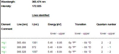
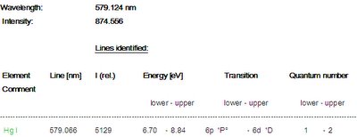


This means for the Hg spectrum:
A.The lines at 404 nm, 435 nm and 546 nm are all decaying from the electronic level 7s2S with energy 7.73 eV. These there lines show an intensity distribution as given by the intensity values of the SpecLine database.
B. The line at 365 nm is decaying form the electronic level 6p2P° with energy 8.85 eV and the line 579 nm is decaying from the electronic level 6p1P° with energy 8.84 eV. Allthough these lines have a higher probability to decay than the lines form the 7s2S level, the denstiy of atoms in the 6p levels is much smaller due to the higher energy of the excited level (8.85 eV and 7.73 eV for the 7s level).
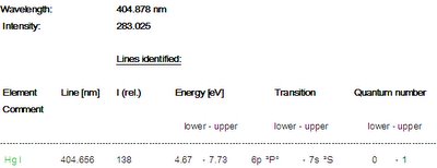
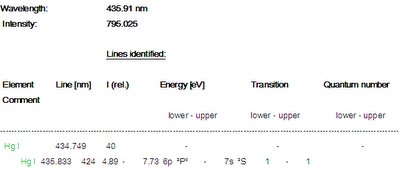
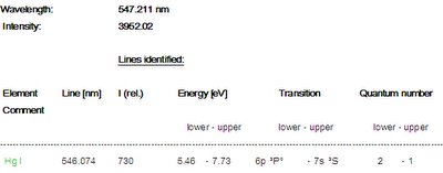


In general, the intensity of a line is ruled first by the excitation process (i.e. the energy of the higher electronic level) and second by the probabilty of decaying from the higher level to a lower level.

The remaining differences in the intensities of the lines is due to the sensitivity distribution of the EmiCon system, i.e. the system is most sensitive between 450 and 550 nm and less sensitive below 400 nm.
~~~ supported by Dr. Thomas Schütte of PLASUS ~~~

2005/12/26

Multi-channel plasma monitoring and controlling system is available


It has been taking a long time to develop the multi-channel plasma emission monitoring and controlling system. I'm very appreciated in so many friends and customers who devoted themselves in the testing and gave us their great supports. Here is a picture for the product family.

More information will be updated later.

2005/07/14

In-vacuum optics protection device

Plasma process is extremely exciting and any in-vacuum optics is easily contaminated by unexpected coatings on mirrors or lenses which are essential to keep the best optical performance for metrology instruments. A special designed in-vacuum optics protection device is able to prevent most of the strong contaminations from the plasma processes, such as sputtering, plasma-CVD or etching. With applying this device, the monitoring stability of plasma process control is assured and preventive maintenance is extended tremendously as well.

~~~ Supported by Dr. Thomas Schütte of PLASUS ~~~

2005/07/13

Welcome to Plasma Circus

Plasma Circus welcomes everyone to join us to introduce new plasma tools or devices that can improve the plasma technology or create new plasma applications. Please post your articles and pictures. Any problem encountered in your plasma applications is also welcome to post them for public discussions.