2012/07/02

Homogeneity & Uniformity

Definitions

Usually the definitions of two important quality factors - homogeneity and uniformity - are easily mixed up in a deposition process no matter which coating technologies are involved.  Note that many articles, papers or technical notes made the same confusion.  So, the definitions must be clear.


Homogeneity generally considers a very local spot area and measure/check the layer properties along the direction of the layer grown.


Uniformity considers the differences or tolerances among several measured data along one axis or on a big XY-plane area.


PEM system normally takes the responsibility of layer’s homogeneity control.


Uniformity can be achieved if the process chamber has a good layout or configuration for reactive plasma process.


Homogeneity

To achieve a good homogeneity layer, PEM system was introduced to reactive plasma processês to ensure the composition fraction (or alloy fraction) in each compound or molecules formed by the reactive plasma process is nearly constant.


In general, a PEM system is able to handle magnetron reactive sputtering in a distance range 500mm-600mm along the long axis of magnetron for a good PID closed loop control under the operating pressure range: approx. 0.8mTorr~10mTorr. In this example, a SiOx layer is grown by a dual magnetron sputtering sources with a process control by a PEM system.  PEM system varies the oxygen flow quickly to fit the setpoint by a fast response PID calculation to give a feedback voltage to control the oxygen flow rate.  A good PID closed loop control can bring the alloy fraction factor x in each grown SiOx layer has an almost constant x value in different growth time, for example:  T1, T2, T3 and T4.

This is what PEM system contributes to get a high homogeneity layer.


Uniformity

Uniformity is a very important factor to be concerned and it’s very complicated because there are many factors that can influence it.  Generally, process chamber’s configuration is most critical to get a good uniformity of the grown layer.


This example has 3 measuring points over the width 1300mm of the PET film to compare the thickness, refractive index and other data corresponding to the uniformity in 3 locations in the same XY-plane on the surface of PET film.


The factors often influencing the uniformity include:


-Pumping: if the pumping ports can not provide good pumping speed and the gas distribution inside the process chamber is not good, the uniformity would be influenced.

-Gas piping: if the gas piping delivering the reactive gas can not deliver the gas into the reactive plasma zone in the shortest time evenly, the uniformity would be influenced.

-Magnetrons: if magnetic constraint for electrons is not uniform, the uniformity would be influenced.

2012/02/04

Advanced Microwave Plasma Source and EMICON plasma monitoring

An R&D for an advanced microwave plasma source with EMICON spectroscopic plasma monitoring technique assisted was done recently. A laser beam was introduced to assist the alignment of the collimator to obtain correct plasma information. The MW source is a linear type with a short length.  It can be scaled up to 3.2m long in dual magnetrons coupled configuration.


Contributed by: PLASUS  and  IBF Electronic GmbH & Co. KG

2011/12/10

A New Honey Comb Device To Protect Expensive Quartz Window Of View Port

In the past years, a new honey comb device which provides a solution to solve the contamination problem on quartz window of view port was developed.  From time to time, the contamination on the quartz (or pyrex) window of the view port in the processes of plasma CVD, etching, sputtering, arc PVD, evaportation PVD always causes higher maintenance costs and lower productivity.  Nowadays a state-of-the-art honey comb device is well-developed.

Fig. 1  Temperature duration up to 600°C without
                center ring in CF type.  In KF type with center
               ring,the maximum temperature is up to 200°C.

There are several selections to fit the view port's type and dimension.  With the aid of this honey comb protection device, the quartz (or pyrex) window can be protected not to be contaminated.  It's also very easy to clean this device by following some simple instructions.


Fig. 2  Different diameters are available.
We are very appreciated in the pictures provided by PLASUS.

2011/09/14

Advanced EMICON (Emission Controller) system vs. traditional PEM (Plasma Emission Controller) system

A traditional PEM (Plasma Emission Monitor) system in charge of a closed loop control of a reactive sputtering process is well-known established in a variety of coating applications in decades. Normally a high sensitivity PMT (Photo-Multiplier Tube) detector amplifies the light signal coming from plasma zone filtered by a narrow band-pass filter or scattered by a grating system or a monochromator. A long narrow tube with a simple collimating lens installed in front of the filter to block the contamination to the lens from plasma particles typically is mounted very close to the plasma zone and it is suffering high temperature from plasma heating and severe coating on the surface. Along the light path, only the spectra information filtered is able to be monitored and a disadvantage is its band width of the filter is too large for spectra analysis and the control precision is also limited due to very poor optical resolution. Typically a good bandpass filter has CWL (Central Wavelength Length) +/- 2nm and FWHM (Full Width Half Maximum) 10+/-2nm.

An advanced spectroscopic EMICON (EMIssion CONtrol) system equips high precision linear arrayed CCD detector and some revolutionary optics along the light path from plasma zone to the detector. Optical resolution is easily achieved in less than 1.5nm. For some applications request higher optical resolution, a solution is available to obtain 10 times better as well. This is really good for the study of plasma species in the process. EMICON allows the monitoring by multiple line elements and different band spectra in the same LOS (Light-Of-Sight) simultaneously, which an user can easily tell the ratio among different ions, atoms and molecules those involved in the plasma reaction. With the merit of broad band spectral range, the characteristics and behaviors of plasma particles participated in the plasma reaction are realized in detail. To stabilize the plasma reaction, it is possible to establish a closed loop control with PID regression built-in function. An Online QC can be achieved as well through easy-to-use endpoint settings on the software.

2009/07/01

另外一個迷思: PEM的閉鎖迴路控制要用MFC或是PZT valve

這也是個在使用PEM閉鎖迴路控制時,經常遇到的問題:
到底要用MFC (Mass Flow Controller)就能夠擔負製程的重責大任? 還是需要使用PZT valve?

用一個很簡單的模型來分析就可以做出正確的判斷,不會選擇錯誤了。
要達成一個PEM閉鎖迴路控制的製程,需要下列的物件才能完成。
1. 感測頭: 將電漿光譜的光線收集傳遞給偵測器。這通常是由光學鏡頭與光纖組成的硬體,將光訊號傳遞到偵測器做光電訊號的轉換。因為是光速在傳遞訊號,所以需要的時間可以忽略。
2. 偵測器: 有感度十分靈敏的光電倍增管PMT (Photo-Multiplier Tube),通常轉換時間小於1 ns; 另外一種是CCD偵測器,轉換時間大約需要1~2 ms。
3. CPU / MPU軟體處理: 光訊號轉成電的訊號,經由電腦軟體的計算與處理產生可做控制的訊號輸出,需要的時間大約5-10 ms。
4. MFC或是PZT Valve: 控制反應性氣體流量的閥門從接收到電腦傳來的控制訊號到調整閥門開啟的大小到達指定的位置所需的時間,好的MFC最快可以在幾個ms達成,PZT Valve可以在小於1 ms內達成。
5. 氣體管路: 氣體經過氣閥後需要流經氣體管路到達真空噴出的位置,這段時間視真空鍍膜系統的真空抽氣設計來決定長短,通常需要20 ms(系統有很好的真空抽氣設計)到200 ms不等。
6. 擴散: 氣體抵達真空內部的噴嘴位置,會依照當時真空度的製程條件以擴散的方式離開噴嘴到達電漿製程的區域,這段時間通常小於1 ms.

重複這六個步驟就是一個完整的電漿反應性閉鎖迴路的控制流程。
因此,也很容易看出使用好的MFC大致就能滿足這種製程的要求了。

使用PEM在成膜均勻性與均質性的迷思

經常有人認為在真空電漿濺鍍系統上安裝了PEM (Plasma Emission Monitor)或是Emission Controller就可以改善鍍膜的均勻性。把PEM當作神看待,卻不知道這是個大錯特錯的觀念。PEM系統能夠控制鍍膜製程的穩定性,也就是鍍在待鍍物上的膜層的品質是穩定的,在成膜的方向上穩定地把相同品質的薄膜一直鍍到待鍍物上。這是PEM最大的效用,卻無法因為安裝使用了PEM而改善鍍膜厚度在待鍍物的面積分布上的均勻性。

要改善待鍍物表面成膜厚度的均勻性,需要從鍍膜設備的硬體設計下手,舉凡使用的幫浦種類、規格、抽氣位置與供氣的氣導設計,以及製程的條件要求等等。一旦成膜厚度的均勻性能夠達到一定的水準,在來使用PEM讓每個鍍膜控制區域內的成膜品質有最佳化的表現。這樣子才能讓均勻性與均質性的表現兩全其美。

2009/06/27

How long to clean the protection device of collimator

準直鏡頭上的蜂巢式防鍍裝置(honey comb protection device),不是filter,防鍍裝置上的蜂巢結構,主要是靠內徑的大小來阻擋原子與分子在特殊真空壓力下進入蜂巢內管。這是根據自由平均路徑的計算得到的結果。蜂巢結構的深度(此管狀裝置的長度)正好將所有會進入到深處汙染光學鏡片(鏡頭)都擋住。根據準直徑頭擺放的位置來決定多久要清潔一次。PECVD的應用,如果擺放位置正確,可能兩到三年的使用還不需要清潔。大部分需要清潔的應用會是濺鍍(sputtering),有些擺放位置比較接近靶材鍍膜的表面,多久需要清潔一次,很難說得準。若擺放在很近鍍膜區域而且一定會被鍍到的位置,當鍍膜製程的操作壓力高,自由平均路徑短,此時蜂巢裝置的表面很快會被鍍上一層厚厚的鍍膜,就需要經常清潔。如果操作壓力低,自由平均路徑變長,在蜂巢裝置上的鍍膜,會進入管內且表面上的鍍膜雖會增加但是增加速度較慢,此時清潔的時間間隔會拉長不會很頻繁。何時需要做清潔? 可以在EMICON軟體上加以特殊的endpoint設定,在每一個主要的monitoring tracks上都做一個lower limit的設定,一旦所有條件都達到,就可以輸出一個digital TTL signal通知需要清潔了。原理是: 蜂巢結構如果被鍍膜遮蔽,所有的監視譜線的強度會同時減弱,而不是其中的某些譜線強度減弱。因為強度的衰減是全面性的發生,所以很容易由設定的終點條件來判斷是否需要做清潔。

Plasma Emission Monitor (PEM)的分類

Plasma Emission Monitor (PEM)有兩大主流:
(a) lens filter type(濾光片型)
(b) spectroscopic type(分光型)

(a) 濾光片型的每個頻道只能一次看一個波長,如果要看另外一個波長,就需要更換濾光片。通常此濾光片以中心波長為主,向長波與短波方向延展大約各5nm。所以,濾光片型的PEM沒有所謂的光譜解析度,濾光片能看到的是包含很寬廣的一個積分光譜區域。因為全光譜都被此濾光片濾光了,所以通過的光線強度十分微弱,因此需要一個很靈敏的偵測器來取得光線的強度資訊並加以放大成為可以分析使用的電訊號。所以,濾光型的光感應裝置包含: 一個防鍍的準直鏡頭(一根小管子,不是蜂巢)、一片濾光片、一個PMT(Photo-Multiplier Tube)光電倍增管偵測器,來把光的訊號轉成電的訊號。

(b) 分光型的每個頻道使用陣列方式的arrayed CCD分光光譜儀,可同時看到分佈在200nm-1100nm光譜範圍內的2048個光譜譜線資料,光學解析度可達1.4nm。光感應的裝置包含: 一個安裝蜂巢式的防鍍裝置的準直鏡頭、真空內部導光的石英光纖、光纖導光用的真空法蘭、外部導光的石英光纖、arrayed CCD分光光譜儀。

2009/06/19

如何應用OES tool與RGA tool

常有人問道: 對需要精準控制的電漿(等離子)製程(工藝)中,到底要使用OES還是RGA呢?
說明如下:
  • RGA能看到環境的氣體成分比例與變化,但是無法看到實際參與電漿製程(等離子工藝)的物種與變化,OES卻可以。這是最大的差異。
  • 其次,RGA的反應遲緩,OES可以快速反應。 因此,RGA對於製程(工藝)上出了狀況是很難追蹤與了解實際電漿製程(等離子工藝)的變化。只有使用OES才有機會知道製程(工藝)中真實發生的情形,進而可以找到解決之道。
  • RGA可以當做OES的輔助,兩者相輔相成。

結論: OES掌握製程(工藝)的穩定性,RGA去處理整體環境的穩定性。

2008/08/26

Improvement of the response time for a fast PID closed loop control


From time to time, there exists a critical issue to handle multi-channel OES system for a reactive sputtering process which demands high response time of the reactive gas supply. For example, a 3-channel PEM system shown in the figure below has three spectrometers in the PEM controller. Each spectrometer’s configuration has its own recording interval (=exposure time multiplies average number), which might be different from others due to slight differences in the alignments of collimators and the plasma density are different in each gas supply section. For the individual control of each channel, the recording intervals are different, but the spectra data acquisition from spectrometers to the computer’s host software needs to collect all three channels sequentially at a time. That means, if the recording interval settings for 3 channels are 100ms, 125ms, 150ms individually(for example), then the complete system recording interval for a closed loop control is the sum of three individual settings, i.e. 375ms (=100ms + 125ms + 150ms). This result is too bad for a fast PID closed loop control and such kind of control can not provide the highest quality of the film deposited on the substrate. Therefore, the new developed EMICON xMC series is able to acquire spectra data for each channel individually without waiting the others. In this way, each gas supply section can work properly in their optimized configuration to maintain the best quality of the film deposited. The high speed PID closed loop controlled process is achievable finally.


Of course, this technology can be used for any kind of applications with the demands on different settings for the recording intervals, but the response time is demanded to be very high. Now, only Plasus EMICON MC/HR series can do it.


2007/03/17

Basics of plasma spectroscopy

A well-known German professor Dr. Ursel Fantz was invited by IOP for an article "Basics of plasma spectroscopy" which we recommend it to read. Please download the PDF file from this website: http://www.iop.org/EJ/abstract/0963-0252/15/4/S01.

知名的德國學者Dr. Ursel Fantz (烏契兒.芳契博士)受邀在IOP期刊發表一篇文章:"Basics of plasma spectroscopy" (電漿光譜學之基礎),我們推薦值得一讀。請在下面的網站直接下載:
http://www.iop.org/EJ/abstract/0963-0252/15/4/S01.

2006/12/04

二氧化矽雙靶反應濺射鍍膜

採用脈衝直流雙極電源供應器(電壓源),輸出端接到兩支以矽為靶材的磁控濺射源 利用電漿監控系統(PEM)控制氧氣的流量,進行無電弧反應式濺射鍍膜的製程。


Figure 1. 從視窗觀看雙靶濺射鍍膜製程


Figure 2. 左右兩靶的脈衝電流波形(峰值電流70A)


Figure 3. 德國Magpuls的直流脈衝電源供應器

2006/09/16

EmiCon System的工作原理介紹

EmiCon是由兩個英文字組成的,分別是Emission(放射)與Control(控制)。

電漿的形成在於原子或分子上的電子受到外來電場游離,再誘發二次電子撞擊更多的原子與分子產生更多的游離態原子與分子,只要外來電場持續供應且環境維持穩定,電漿就能繼續存在。當不同原子與分子上的電子在高低能階之間跳躍,會釋放與吸收各種特定的能量,釋放的能量可用光的波長形式來詮釋,故同一原子或分子內不同能階軌域的電子產生的跳躍,會同時以不同波長的光把能量釋放出來。分析電漿釋放出來的光譜可以得知參與製程反應的電漿物種,進而找出控制反應機制的主要參數。因此,如何控制與觀察電漿的運動與作用就成為一項艱深的學問。

為了研究存在電漿中的各種不同帶電離子與分子的成分與分布,在不影響電漿反應機制的條件下,還能採用回綬控制的方式來穩定製程,光學偵測法是不接觸電漿也不影響電漿作用的唯一選擇,其中能夠完全表現電漿特性的就是採用分光光譜學的量測技術加上特殊設計的回綬控制機制來達到分析電漿物種與穩定製程的雙重目的。其中以OES (Optical Emission Spectroscopy)光放射光譜學的技術最為成熟。為了達到回綬控制的目的,電漿放射出來的光線經由一個準直鏡光學鏡頭焦聚到石英光纖,傳送到分光儀把電漿的光線用光柵分光到一個陣列式的光偶合感測器(Arrayed CCD),每一個感測器上的獨立感測單元代表一個分光後的特定波長,整個陣列分佈把光的資訊轉化成有用的電壓資訊,電腦透過USB電纜取得這一瞬間電漿光線轉化成陣列對應電壓的光譜資訊,再由軟體針對選定的特殊譜線資料做進一步的PID回綬控制。

下圖為EmiCon回綬控制的示意圖


2006/08/06

多頻道等離子監控系統: EmiCon家族

2006年EmiCon多頻道等離子監控系統全貌。


上層: EmiCon3C and A04D11
3套分光儀: 200nm-850nm (2048 pixels)
4個類比輸出: 直流0-10伏特
2個數位控制點: 1個數位輸入與1個數位輸出

下層: EmiCon3C and A08D44
3套分光儀: 200nm-850nm (2048 pixels)
8個類比輸出: 直流0-10伏特
8個數位控制點: 4個數位輸入與4個數位輸出

Ion Assisted Co-Sputtering (離子輔助共同濺射)

以三支磁控濺射靶加上一個等離子源執行離子輔助共同濺射。其中一支磁控濺射靶接上AE MDX 1.5KW DC電源,另外兩支磁控濺射靶接上兩套Magpuls QP1000/3/35 bp 3KW脈衝直流電源個別執行單極直流脈衝濺射模式(最高頻率可達83KHz,最高電壓可達1000伏特)。等離子源採用Dressler 1.5KW RF射頻電源。下圖為執行離子輔助共同濺鍍時的製程現況。


2006/04/01

Pulsed DC脈衝直流電源不同應用的組合

1. 雙極對稱式輸出
這種組合主要用在同靶材的反應式雙磁控濺射靶的鍍膜製程。SiO2, TiO2, Ta2O5, Al2O3, ITO, AZO等。利用改變脈衝作用與非作用的時間來控制濺鍍電漿的密度高低,在特定的電漿阻抗條件下,可優化濺鍍速率與薄膜品質。組合如下:
1.1 脈衝產生控制器 X 1
型號MAGPULS 1000/30/100 bp
• +/- 0-1000V輸出
• 30安培直流輸出(Max.)
• 100安培脈衝電流輸出(Max.)
1.2 直流電源供應器 X 1
型號MAP 1000/20
• 0-1000V輸出
• 0-25安培直流輸出(Max.)
註:在400伏特的濺鍍製程有最大電流輸出25安培。


2. 雙極非對稱式輸出
這種組態大量用在單靶的反應式濺鍍製程以及氮化物硬膜的治具偏壓用途。也有用於雙靶特殊混合的陶瓷合金濺鍍製程。組合如下:
2.1 脈衝產生控制器 X 1
型號MAGPULS 1000/30/100 bp
• +/- 0-1000V輸出
• 30安培直流輸出(Max.)
• 100安培脈衝電流輸出(Max.)
2.2 直流電源供應器 X 1
型號MAP 1000/3 (供應正電壓)
• 0-1000V輸出
• 0-3安培直流輸出(Max.)
2.3 直流電源供應器 X 1
型號MAP 1000/20 (供應負電壓)
• 0-1000V輸出
• 0-25安培直流輸出(Max.)

2006/03/27

脈衝直流電源問答集

Q1: RF電源在執行反應式鍍膜時,是否也有防Arc的功能? 用何種方式?
A1: RF的電源與DC或是脈衝DC電源一樣有好多種等級,一般可以從RF電源的規格敘述中知曉是否具有抑制與偵測ARC的功能。其原理與直流電源類似,感知突發的大電流所產生的斜率大小來判斷。一旦確認ARC發生,也是將所有供電中止,經過一個延遲的時間後再次觸發電漿,繼續製程。
RF電源也有所謂的脈衝RF電源,主要目的是希望能夠更有效率地防止ARC的發生。

Q2: MAGPULS可設定輸出的Frequency,其作用是在何地方? 會對膜的品質有影響嗎?
A2: MAGPULS與其他電源不同,可以針對製程所需來改變電漿的作用與非作用時間,頻率可以利用週期的倒數計算得到(f=1/T)。其他電源因為設計不同而無法提供如此準確與詳細的作用時間控制方法,只好用頻率來說明他們的作用時間。

作用時間的長短會依製程的不同產生電漿製程的控制參數之間的移轉。當作用時間越短,越是偏向電壓控制模式,也就是實際作用的電壓會接近或等於設定的電壓值。當作用時間變長,電壓會逐漸降低,且脈衝電流與平均值流電流會增加,直到達到飽和電流,此時,無論增加任何作用時間將無法再增加脈衝電流與直流電流。
利用這種作用時間的可調性,可以改變電漿製程達到調製不同的薄膜品質的目的。

Q3: 在執行非對稱式濺鍍並加偏壓時,磁控靶是否都使用負輸出,而偏壓使用正輸出,可加強膜的附著力?
A3: 濺鍍靶的靶面都是接到低電位的極性。MAGPULS採用正電場的觀念,輸出端的正與負代表電場方向由正(高)往負(低)。所有UP+與DC+都是把正端(高電位)接到真空腔體上接地,負端(低電位)接到靶材,這樣子才能把Ar離子加速撞擊靶材產生濺鍍。如果正負端正好接反了,只要在MAGPULS內部選用相反極性的模式操作就可以了。因為”負負得正”的道理,很簡單的。

加了偏壓當然對薄膜的附著力有增強的效果。用正電場的觀念,在加偏壓的待鍍物上必須接低電位(UP+模式的負端)。

Q4: 抑弧參數可自行設定,但其參考依據為何?
A4: MAGPULS在輸出端安裝有一個高速的電流感測器,可以同步感知透過輸出迴路帶回來的電漿狀態,當電漿製程發生電弧,電流感知器立即將此突發的脈衝電流與比流器(comparator)中設定的Arc-Level數值比對,如果感知器的數值高於Arc-Level的設定值,MAGPULS就把這次的比對當作偵測到一次電弧。接著由MAGPULS內部的電腦計算累計偵測到的電弧次數是否在設定的時段內達到預先的設定數目,再來判定是否要在LCD面板上顯示電弧發生的次數。

要判斷是否為真正的電弧,只要從較短的作用時間做起,慢慢地把作用時間加長,同時把電流的Arc-Level設定值也加大,直到沒有任何的ARC記錄顯示在LCD為止。如果Arc-Level放到最大還有ARC記錄顯示,這代表電漿製程內真的有電弧的發生。

Q5: 學術單位執行反應式濺鍍時多用RF,若改用MAGPULS可將濺鍍速率提高多少?還有哪些優點?
A5: 舉一個鍍TiO2的例子做比較:
RF最大的飽和鍍膜速率: 1500nm/h,也就是4.16Å/s
DC Pulsed的普通濺鍍速率在40Å/s以上
兩者大概差十倍。其他材料也都大同小異。

優點:
1. 磁控靶的最大功率限制才是DC Pulsed的鍍膜速率上限。如果磁控靶可以耐到20KW,你用一套10KW的Pulsed DC就無法發揮最大的鍍膜速率。但是RF的先天限制,其飽和鍍膜速率一旦達到,無論電源的功率提高多少都無法再增加任何一點的鍍膜速率。
2. ARC可以很有效控制。
3. 擴大製程可調整的空間,可以變動作用時間與電流參數做出不同品質的薄膜。

2005/12/28

703nm 重要的氟譜線

多數的電漿系統會用到CF4, SF6等氣體在鍍膜或是蝕刻的製程中,而氟的殘留物都是不允許的。EmiCon系統可以有效偵測出製程中與結束前的氟含量,利用703nm的氟譜線可以知道製程中的氟含量。方法簡易而有效。


使用內真空感測器可以隨意安置,取得最佳的製程監測方位。

2005/12/27

What's the difference between the intensity listed in the database and the actual measurement?

This is an interesting question asked often while one touches and senses the plasma by optical emission spectrometry.

The radiation we are measuring with the EmiCon OES system is due to a two-step process in the plasma:
1. Ground state atoms are excited by electron collisions in higher electronic levels. The density of the excited atoms in a specific electronic level depends on the energy gap between the ground state (0 eV) and the higher electronic level and the electron temperature (i.e. electron energy distribution function EEDF, often Maxwelliam). The larger the gap the less is the density of the atom in this specific energy level.
2. From the higher electronic level the atom is decaying by spontaneous emission to some lower electronic level. This is the radiation we are measuring. The intensity given in the SpecLine database is the probability that the atom in the specific higher electron level will decay into the given lower electronic level.


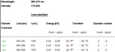
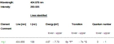
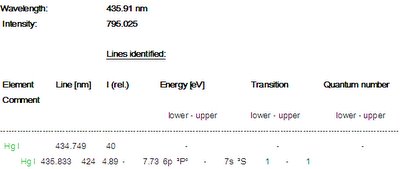
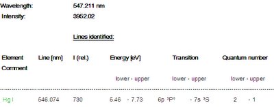
This means for the Hg spectrum:
A.The lines at 404 nm, 435 nm and 546 nm are all decaying from the electronic level 7s2S with energy 7.73 eV. These there lines show an intensity distribution as given by the intensity values of the SpecLine database.
B. The line at 365 nm is decaying form the electronic level 6p2P° with energy 8.85 eV and the line 579 nm is decaying from the electronic level 6p1P° with energy 8.84 eV. Allthough these lines have a higher probability to decay than the lines form the 7s2S level, the denstiy of atoms in the 6p levels is much smaller due to the higher energy of the excited level (8.85 eV and 7.73 eV for the 7s level).


In general, the intensity of a line is ruled first by the excitation process (i.e. the energy of the higher electronic level) and second by the probabilty of decaying from the higher level to a lower level.

The remaining differences in the intensities of the lines is due to the sensitivity distribution of the EmiCon system, i.e. the system is most sensitive between 450 and 550 nm and less sensitive below 400 nm.
~~~ supported by Dr. Thomas Schütte of PLASUS ~~~

2005/12/26

Multi-channel plasma monitoring and controlling system is available


It has been taking a long time to develop the multi-channel plasma emission monitoring and controlling system. I'm very appreciated in so many friends and customers who devoted themselves in the testing and gave us their great supports. Here is a picture for the product family.

More information will be updated later.